DOT GAIN
DOT GAIN OR TONE VALUE INCREASE
What is dot gain and how it can be measured?
To answer these questions, let us see what dot gain is, how it is measured, how its value affects the tone rendition and how dot gain can be controlled.
The term “dot gain” is currently “outside the law", it is a slang expression. On the 1st of January 2011, “THE NATIONAL STANDARD OF THE RUSSIAN FEDERATION, GOST R ISO 12647-1-2009: Graphic technology. PROCESS CONTROL FOR THE PRODUCTION OF HALF-TONE COLOR SEPARATIONS, PROOF AND PRODUCTION PRINTS. Part 1. PARAMETERS AND MEASUREMENT METHODS” entered into force, in which “the formerly known term “dot gain” is not recommended for use” (paragraph 3.45, Note 3). Instead of it, it is proposed to use the term “tone value increase”, or abbreviated TVI. But in spite of this, people have applied it, and they do not refuse to stop applying the term “dot gain”. The expression is too good and meaningful. It precisely defines the essence of the process. The result is the revolutionary situation: the lower classes cannot because they have not read the standard, and the top classes do not work because the lower classes would not understand them. In 2007, it was proposed to distinguish between these two terms to resolve this revolutionary situation.
Dot gain (Z) - is the expansion of the printed elements area during the printing process. It is defined as the difference between the relative areas of the printed element on the form and the area of the ink element on the impression. The production printing plate should not be confused with the photomechanical or the electronic document.
Tone value increase (tone value increase) - is the difference between the tone values for impression and the tone values on the screen photomechanical or in the digital file.
To control the tone value increase, it is necessary to understand how and what affects the parameter which you are going to control. So let us discuss the main factors influencing the dot gain. The dot gain value is determined by two types of factors: mechanical and optical.
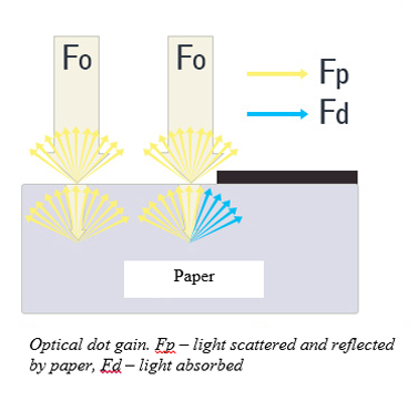
If the paper has transparency, a part of the light flux penetrates it and disperses in the paper web. Some light Fd scattered in the paper web is absorbed by the ink layer. Thus, the halftone value on translucent paper is higher than the halftone value of the ink elements with the same area, printed on the opaque coated paper, that is, the printed elements are optically larger by area than they actually are. More or less, any coated paper has transparency and, consequently, optical dot gain is always present.
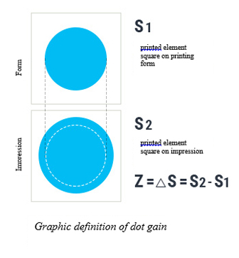
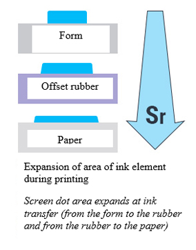
MEASUREMENT OF DOT GAIN IS BASED ON MEASUREMENT OF RELATIVE SQUARE OF PRINTED ELEMENT ON PRESS PLATE (SP) AND ON IMPRESSION (SR) AND CAN BE DONE BY TWO METHODS.
DENSITOMETRIC APPROACH
Densitometric approach is based on measuring the 100% optical density of monochrome tint (Ds) and the optical density of the measured field (Dr). The relative square of the printed element is calculated by Sheberstov-Murray-Davis formula, where n is Yule-Nielson light scattering coefficient, equals 1 by default. The dot gain is calculated as follows: Zr = Sr - Sp. Densitometric method is basic in measuring the dot gain. A densitometer is enough as it makes dot gain calculation automatically. But densitometric method has a number of serious shortcomings.

At printing on high-quality opaque coated paper with low light scattering, it is quite easy to measure the dot gain, but at printing on light coated paper, uncoated paper and paper with high transparency and high values of light scattering, the error of measurement may reach critical values.
THE BELOW RULES SHOULD BE OBSERVED TO OBTAIN THE ADEQUATE RESULT

It is recommended to measure the halftone values and screen tints on the non-reflective black backing. Otherwise, the result of measurement may affect the images printed on the reverse side of paper

Measure only special screen fields intended for determining the dot gain (usually they are located on the control scale)

To calculate the relative square of the printed elements, it is necessary to apply the required Yule-Nielson coefficient, allowing to consider the light scattering, that is, to correct the error of measurement. The variation range of Yule-Nielsen coefficient is 1 to 3. The greater the internal light scattering of paper, the greater is the coefficient value. For example, for the glossy offset paper with light coating n=1.2–1.25.

MICROPHOTOGRAPHY OF BLACK TINT WITH THE TRACE OF PICKING
The error of dot gain measurement may occur due to incorrect measurement of the 100% optical density of tint Ds.
At printing on paper with a faint surface layer, on screen fields that excess 90%, white noise with probability distribution is observed, and it results fr om the picking – the destruction of the surface layer of paper. As a result, the measured 100% optical density of tint is undervalued and, respectively, the calculated dot gain value is too high.
COLOR DILUTION APPROACH
To measure the color coordinates, the color grader with geometry 45/0 or 0/45 is used at standard conditions of observations under ICE 1931 2 ° and D50 light source. These three-stimulus values are measured for unsealed material, selected screened area and the tint which is the nearest to the screened area.
PERCENTAGE IS CALCULATED BY FORMULAS (1), (2), (3):
FOR CYAN
A = 100 ( X0 - XP ) / ( X0 - XП ) (1)
FOR MAGENTA AND BLACK
A = 100 ( Y0 - YP ) / ( Y0 - YП ) (2)
FOR YELLOW
A = 100 ( Z0 - ZP ) / ( Z0 - ZП ) (3)
WHERE:
| X0, Y0, Z0 |
color coordinates of unsealed material |
| Xp, Yp, Zp |
color coordinates of screened area |
| Xn, Yn, Zn |
tint color coordinates |
To ensure sufficient accuracy, the diameter of the scanning aperture of the device must be at least 15 or at least 10 halftone periods. This requirement is also applied to the non-circular scanning apertures by analogy. For aperiodic screens, the aperture should be even greater than that required for periodic screens, usually used with the evaluated printing material.
Note: - The results can be 2% lower than those obtained by densitometric method, especially for cyan.
PHOTOMETRIC APPROACH
Photometric method of measurement is based on registration (photographic or electronic) of enlarged image of the screen field and determining the number of cells of the metering sensor, which account for ink elements.

PHOTOMETRIC APPROACH OF SCREEN DOT SQUARE MEASUREMENT: SR=AI/AС, WHERE AI IS THE QUANTITY OF CELLS COVERED BY THE INK ELEMENT, AС IS THE OVERALL QUANTITY OF CELLS
Today, the production uses only electronic method of registration, as the photographic method is very laborious and time consuming.
The photometric method uses a special device designed to determine the relative square of the printed elements on the printing plates – a platereader. It works similarly to an ordinary digital camera: enlarged view of the printed element enters on the image sensor and the number of pixels falling on the screened elements is fixed. The ratio of the number of pixels of the screened elements to the total effective number of pixels of the sensor is the relative square of these elements.
Photometric method for measuring the dot gain has no flaws that are inherent in densitometric approach. Although this method also has a number of important features: the measurement process is longer in comparison with the densitometric measurements and the accuracy of the result depends strongly on the instrument setting (which is done automatically).
INK SPREAD AND DOT GAIN
In Russian, the word “ink spread” is used for translation of the English expression “dot gain”. Although they mean the same thing, yet there is a significant difference between them.
It is clear from the article that dot gain is a change in the dot size from the printing form to the impression.
Dot gain means the same thing, but from a digital file to impression. That is, it considers the percentage of the screen dot change at all intermediate stages: transformation at the nonlinear recalculation in the raster processor, change of the dot size due to non-linearity of the output device, “staining” of the dot at the exposure in the printing frame, etc.
Such terminology mismatch sometimes leads to confusion. In particular, in the old printing books published in the Soviet Union, it is pointed out that a good ink spread is considered to be 8-10%. When the first version of the program Adobe Photoshop had appeared, the user was surprised to learn that the famous “European standard” gives an 18% dot gain. Does it mean that the printing standards were much stricter in the USSR than the foreign standards? Not really. The fact is that the ink spread and dot gain are different things. And, accordingly, they should be measured and assessed differently. In particular, when the user measures the 50% field of the control scale field on the impression, and the scale is displayed on the film in photocomposition along with the main image, the user measures the dot gain (this is what the meter informs about), and not the ink spread in the classical understanding. The article describes the correct way of measuring the dot gain. Therefore, in a dispute with the printing house on what dot gain is needed, one should first agree on the terms.
HOW DOT GAIN AFFECTS THE GRAY-LEVEL IMAGE REPRODUCTION

NORMAL DOT GAIN

ALLOWED DOT GAIN EXPANSION

OVERSIZED DOT GAIN

EXCESSIVE DOT GAIN
WHAT DOES THE DOT GAIN DEPEND ON?
PRINTING BASE
PRINTING BASE
Spraying almost directly depends on the diffusion and optical properties Basis. In most cases, the printed substrate is paper. It is she who causes Optical dot gain.
INK
INK
Its physical, mechanical and optical properties.
PRESSURE
PRESSURE
Between mechanical pairs in the process of printing (crushing).
RIGHT DELIVERY OF SHEETS
RIGHT DELIVERY OF SHEETS
In the process of printing on multi-color sheet-fed printing presses (Doubling).
DIFFERENCES IN LINEAR SPEEDS AND DIFFERENCE OF DIAMETERS
DIFFERENCES IN LINEAR SPEEDS AND DIFFERENCE OF DIAMETERS
Offset cylinders for rolling machines and the difference in diameters Offset cylinders in comparison with the diameter of printing cylinders for sheet machines (Slippage, crushing) ..
PERIMETER
PERIMETER
The size and shape of the printed element, or rather its perimeter. The round point has the least Other things being equal. The larger the perimeter of the printed element, the greater The dot gain Z.
The dot gain curves are not built under production conditions. The dot gain is measured at two supporting points: 40% or 50% and 75% or 80%. The 50% dot gain of the screened element is standardized not only in the printing house, there is a state standard OST 29.66-90 (since Soviet times) and a modern European standard ISO 12647–2. The standards give recommended zonal dot gain values and the deviation from the recommended value of 50% of the screen dots for different types of paper and printing presses. The customer has the right to demand from the printing house to comply with the standard requirements. In the European standard, in addition to the recommended dot gain values, there is a concept of “midtone scatter” or “midtone spread”. This is the difference between the maximum and the minimum values of the ink dot gain deviation from the recommended value:
| S=max[(Ac-Aco) | (Am-Amo) | (Ay-Ayo)] – min[[(Ac-Aco) | (Am-Amo) | (Ay-Ayo)]
Ac - measured value of cyan ink dot gain of 50% of ink element;
Aco - standardized value of cyan ink dot gain;
Am - measured value of magenta ink dot gain;
Amo - standardized value of magenta ink dot gain;
Ay - measured value of yellow ink dot gain;
Ayo - standardizeed value of yellow ink dot gain.
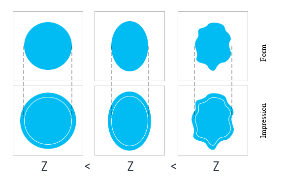

VARIATION OF DOT GAIN VALUE AT CHANGE OF SCREEN DOT SHAPE
Since the dot gain value depends on the dot perimeter, the more complex the dot shape is, the greater is the dot gain. A circular screen dot has the minimum dot gain.

DOT GAIN COMPENSATION
Correct setting of the dot gain parameters is the basic requirement for work with the images. If the set value is incorrect, or, for example, it is set “by default”, then the end result may be unpredictable, though everything looks decent on the screen. These are elementary actions, but they are often overlooked, or one simply makes little of them. Nevertheless, Adobe Photoshop includes all necessary that one needs to set the dot gain, and all dot gain types are available, both by one number, and at a special curve.
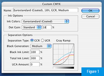
The easiest way of setting the dot gain is shown in Figure 1. This is the standard dot gain for the “European standard”. In this case, it is set by a single number. But it should be borne in mind that in this case the ink spread is set as such, and it is not the dot gain parameter. They are similar, but there is difference between them. However, if one sets the dot gain parameters here, this would not be a big mistake, as the photographic readout is usually linearized in maximum, though this is not always possible.
However, such approach may be too simplistic. The dot gain can vary in the printing sections, moreover, the dot gain curve may have a more complex shape than when using only one number. In this case, the program allows setting the compensation by a special curve instead of the number. The curve is obtained at setting the parameters in several measured areas (in this case, they are 10%, 40% and 80% fields of gray scale).
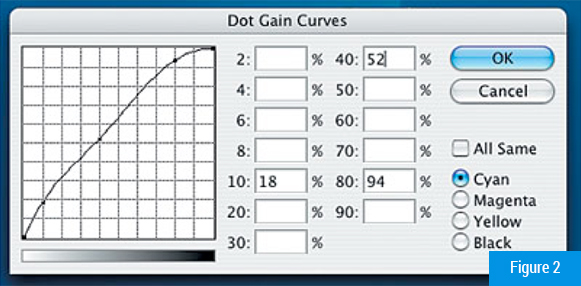
It should be noted that in case of using the numerical dot gain values in Adobe Photoshop, the dot gain is automatically valued as a dot gain on 50% field (this is the way the things are done in America wh ere Photoshop comes from). In Europe, the dot gain measurement by two fields is typically used (for example, 40, 80 or 45, 75). Thus, if one ascertains the dot gain value in the printing house and receives in response one number (20% in Russia), it would be useful to ask what field it is measured by. If the field is 50%, it can be safely set as a numerical value, and if by any other field, one will have to use the curve. By the way, those curious can at their leisure try “playing” with a dot gain value in the box in Figure 2. And see what will happen with the image.
The fact is that the dot gain range defined by the standard is quite high, in addition, the deviations from the recommended values for different CMY colors can vary. As a result, one may receive a serious color imbalance. For example, if the dot gain value of one of the inks increases by the maximum value permissible by the standard, and the dot gain value of the remaining inks also increases, the overall color balance of the image will not change. There will be only a slight loss of shade gradations. But if the deviation of one or two inks will be in different directions even within the standard limits, there will be obvious deviations in color that in some cases cannot be compensate by the changes in the ink layer thickness.
The customer may require from the printing house to follow the requirements of the standard. However, due to physical deterioration of the equipment, many printing houses are not able to meet the requirements of the standard for dot gain, even at following all technological standards.
INK LAYER THICKNESS
(OPTICAL DENSITY OF THE SUPPLIED INK)
The thickness of the ink layer is practically the only variable parameter, allowing the adjustment by the color during the printing process. The increased ink thickness invariably leads to an increase in dot gain. This parameter is standardized by internal documents in most printing houses, so ideally it is considered constant.
In this article, we will not describe in details the reasons for dot gain. As one can see, there are many reasons. It is important to measure it correctly and to be able to evaluate the results.
So, we have already discussed what the dot gain is and how it is measured, now let us discuss what can be done with it.
As it has been already mentioned, the dot gain curve determines the gradation curve of the printing process, which in turn affects the color reproduction of images during printing. In most cases, the dot gain, rather than the optical density, determines the color reproduction. Thus, the dot gain control is a prerequisite for obtaining a satisfactory result.
There is nothing wrong if the dot gain value exceeds the norm by 5–7%. This usually results from the measurement errors.
Thus, control of dot gain is a prerequisite for obtaining a satisfactory result. There is nothing wrong if the dot gain value exceeds the norm by 5–7%. This usually results from the measurement errors.
GRADATION CURVE OF PRINTING PROCESS
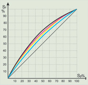
Non-linear shape is determined by the presence of dot gain. The more bent the curve, the higher the dot gain.
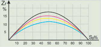
The dot gain diagram is sometimes built for more prominence.
SEVERAL RULES
Several rules should be observed at evaluation of the dot gain
-
If there is any doubt in measurement results (e.g., visually the field corresponds to a predetermined percentage of the screen field, and the densitometer shows the dot gain that excesses 20%), it is necessary to measure by the other method or, if this is not possible, repeat printing on the more dense coated paper with high quality coated layer without changing the press settings and compare the results. If this is impossible, continue printing, as it is likely to be a measurement error.
-
Usually, the high dot gain values are caused by ghosting of screen dots and not by the pressure between the printing couples or low ink viscosity. Ghosting is often observed on the sheet-fed presses in the shops that are not equipped with climate control, at printing on the low density paper. A characteristic feature of ghosting is significant difference in the dot gain in the sheet flap and tail. It is almost impossible to eliminate this defect completely without conducting serious operations (purchase of a and adjusting the transmission valves, etc.) is almost impossible.
-
Ghosting, splitting, slipping, excess pressure between the printing couples increase the dot gain and are the defects that lead to spoilage. And the customer has the right to demand elimination thereof.
DOT GAIN IS A NATURAL PHENOMENON, AND IF IT IS NOT AGGRAVATED BY THE DEFECTS, DESCRIBED IN THE THIRD PARAGRAPH, IT SHOULD BE PERCEIVED AS A MATTER OF COURSE.
It is almost impossible to remove it. It must be taken into account at color separation and screening. Therefore, the main requirement for the dot gain is predictability and consistency.
